Recently, my teammate Jessica wrote an excellent intro blog post about VPP. VPP is an open source user-space networking framework that we're looking into at Igalia. I highly recommend reading Jessica's post before this post to get aquainted with general VPP ideas.
In this blog post, I wanted to follow up on that blog post and talk a bit about some of the details of plugin construction in VPP and document some of the internals that took me some time to understand.
First, I'll start off by talking about how to architect the flow of packets in and out of a plugin.
How and where do you add nodes in the graph?
VPP is based on a graph architecture, in which vectors of packets are transferred between nodes in a graph.
Here's an illustration from a VPP presentation of what the graph might look like:
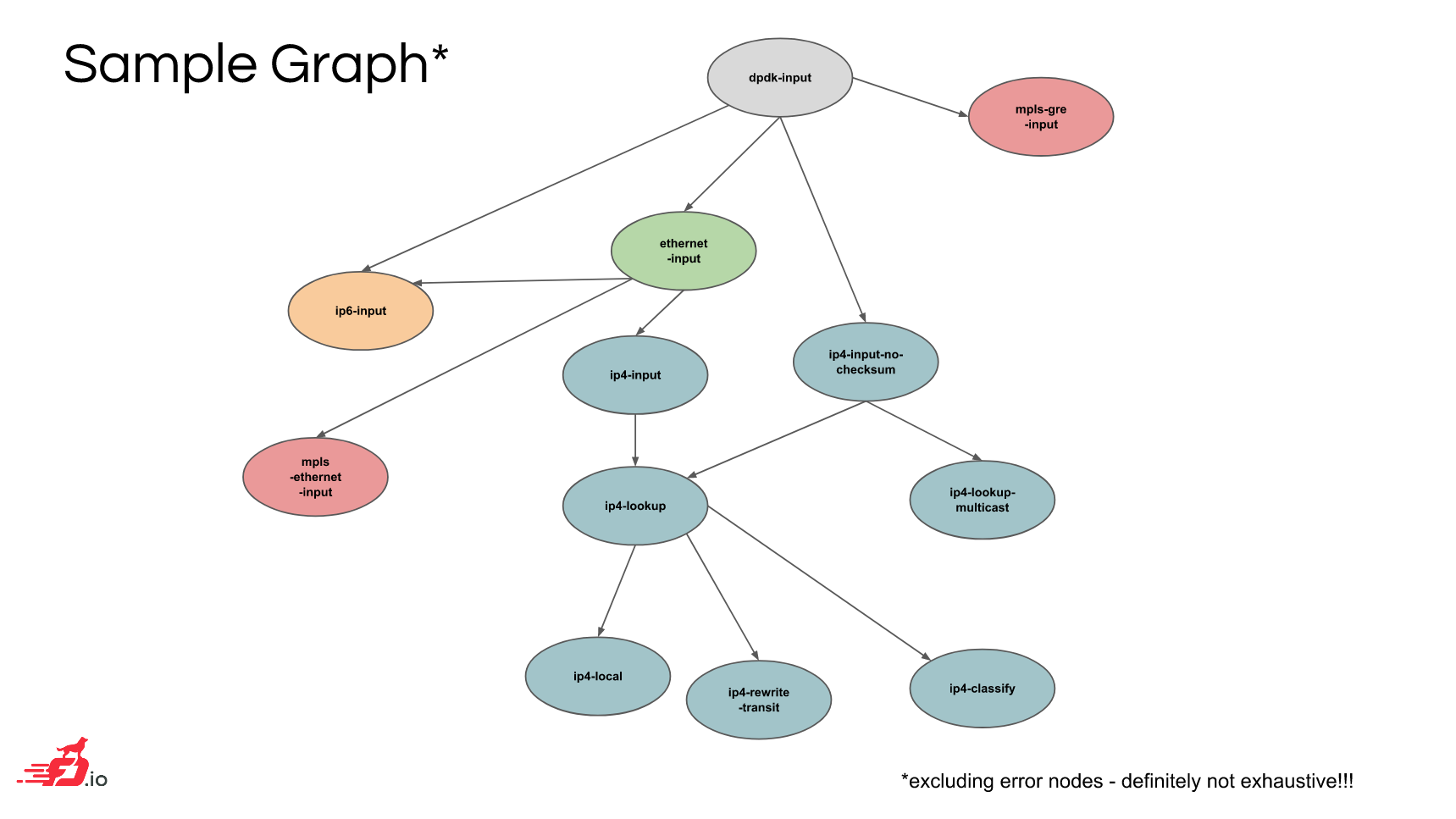
(source: VPP overview from fd.io DevBoot)
One thing that took me a while to understand, however, was the mechanics of how nodes in the graph are actually hooked together. I'll try to explain some of that, starting with the types of nodes that are available.
Some of the nodes in VPP produce data from a network driver (perhaps backed by DPDK) or some other source for consumption. Other nodes are responsible for manipulating incoming data in the graph and possibly producing some output.
The former are called "input" nodes and are called on each main loop iteration. The latter
are called "internal" nodes. The type of node is specified using the vlib_node_type_t type
when declaring a node using VLIB_REGISTER_NODE.
There's also another type of node that is useful, which is the "process" node. This exposes a thread-like behavior, in which the node's callback routine can be suspended and reanimated based on events or a timer. This is useful for sending periodic notifications or polling some data that's managed by another node.
Since input nodes are the start of the graph, they are responsible for generating packets from some source like a NIC or pcap file and injecting them into the rest of the graph.
For internal nodes, the packets have to come from somewhere else. There seem to be many ways to specify how an internal node gets its packets.
For example, it's possible to tell VPP to direct all packets with a specific ethertype or IP protocol to a node that you write (see this wiki page for some of these options).
Another method, that's convenient for use in external plugins, is using "feature arcs". VPP comes with abstract concepts called "features" (which are distinct from actual nodes) that essentially form an overlay over the concrete graph of nodes.
These features can be enabled or disabled on a per-interface basis.
You can hook your own node into these feature arcs by using VNET_FEATURE_INIT:
/**
 * @brief Hook the sample plugin into the VPP graph hierarchy.
 */
VNET_FEATURE_INIT (sample, static) =
{
  .arc_name = "device-input",
  .node_name = "sample",
  .runs_before = VNET_FEATURES ("ethernet-input"),
};
This code from the sample plugin is setting the sample node to run on the device-input
arc. For a given arc like this, the VPP dispatcher will run the code for the start
node on the arc and then run all of the features that are registered on that arc. This
ordering is determined by the .runs_before clauses in those features.
Feature arcs themselves are defined via macro:
VNET_FEATURE_ARC_INIT (device_input, static) =
{
  .arc_name  = "device-input",
  .start_nodes = VNET_FEATURES ("device-input"),
  .arc_index_ptr = &feature_main.device_input_feature_arc_index,
};
As you can see, arcs have a start node. Inside the start node there is typically some code that checks if features are present on the node and, if the check succeeds, will designate the next node as one of those feature nodes. For example, this snippet from the DPDK plugin:
/* Do we have any driver RX features configured on the interface? */
vnet_feature_start_device_input_x4 (xd->vlib_sw_if_index,
                    &next0, &next1, &next2, &next3,
                    b0, b1, b2, b3);
From this snippet, you can see how the process of getting data through feature arcs is kicked off. In the next section, you'll see how internal nodes in the middle of a feature arc can continue the chain.
BTW: the methods of hooking up your node into the graph I've described here aren't exhaustive. For example, there's also something called DPOs ("data path object") that I haven't covered at all. Maybe a topic for a future blog post (once I understand them!).
Specifying the next node
I went over a few methods for specifying how packets get to a node, but you may also wonder how packets get directed out of a node. There are also several ways to set that up too.
When declaring a VPP node using VLIB_REGISTER_NODE, you can provide the .next_nodes argument
(along with .n_next_nodes) to specify an indexed list of next nodes in the graph. Then you can
use the next node indices in the node callback to direct packets to one of the next nodes.
The sample plugin sets it up like this:
VLIB_REGISTER_NODE (sample_node) = {
  /* ... elided for example ... */

  .n_next_nodes = SAMPLE_N_NEXT,

  /* edit / add dispositions here */
  .next_nodes = {
        [SAMPLE_NEXT_INTERFACE_OUTPUT] = "interface-output",
  },
};
This declaration sets up the only next node as interface-output, which is the node that
selects some hardware interface to transmit on.
Alternatively, it's possible to programmatically fetch a next node index by name using
vlib_get_node_by_name:
ip4_lookup_node = vlib_get_node_by_name (vm, (u8 *) "ip4-lookup");
ip4_lookup_node_index = ip4_lookup_node->index;
This excerpt is from the VPP IPFIX code that sends report packets periodically. This kind of approach seems more common in process nodes.
When using feature arcs, a common approach is to use vnet_feature_next to select a next
node based on the feature mechanism:
/* Setup packet for next IP feature */
vnet_feature_next(vnet_buffer(b0)->sw_if_index[VLIB_RX], &next0, b0);
vnet_feature_next(vnet_buffer(b1)->sw_if_index[VLIB_RX], &next1, b1);
In this example, the next0 and next1 variables are being set by vnet_feature_next based
on the appropriate next features in the feature arc.
(vnet_feature_next is a convenience function that uses vnet_get_config_data under the
hood as described in this mailing list post
if you want to know more about the mechanics)
Though even when using feature arcs, it doesn't seem mandatory to use vnet_feature_next. The
sample plugin does not, for example.
Buffer metadata
In addition to packets, nodes can also pass some metadata around to each other.
Specifically, there is some "opaque" space reserved in the vlib_buffer_t
structure that stores the packet data:
typedef struct{

/* ... elided ... */

u32 opaque[10]; /**< Opaque data used by sub-graphs for their own purposes.
                  See .../vnet/vnet/buffer.h

/* ... */

} vlib_buffer_t;
For networking purposes, the vnet library provides a data type
vnet_buffer_opaque_t
that is stored in the opaque field. This contains data useful to networking
layers like Ethernet, IP, TCP, and so on.
The vnet data is unioned (that is, data for one layer may be overlaid on data for another) and it's expected that graph nodes make sure not to stomp on data that needs to be set in their next nodes. You can see how the data intersects in this slide from an FD.io DevBoot.
One of the first fields stored in the opaque data is sw_if_index, which is
set by the driver nodes initially. The field stores a 2-element array of input and output interface
indices for a buffer.
One of the things that puzzled me for a bit was precisely how the sw_if_index
field, which is very commonly read and set in VPP plugins, is used. Especially
the TX half of the pair, which is more commonly manipulated.
It looks like the field is often set to instruct VPP to choose a transmit
interface for a packet.
For example, in the sample plugin code the index is set in the following way:
sw_if_index0 = vnet_buffer(b0)->sw_if_index[VLIB_RX];

/* Send pkt back out the RX interface */
vnet_buffer(b0)->sw_if_index[VLIB_TX] = sw_if_index0;
What this is doing is getting the interface index where the packet was received and then setting the output index to be the same. This tells VPP to send off the packet to the same interface it was received from.
(This is explained in one of the VPP videos.)
For a process node that's sending off new packets, you might set the indices like this:
vnet_buffer(b0)->sw_if_index[VLIB_RX] = 0;
vnet_buffer(b0)->sw_if_index[VLIB_TX] = ~0;
The receive index is set to 0, which means the local0 interface that is
always configured. The use of ~0 means "don't know yet".
The effect of that is (see the
docs
for ip4-lookup) that a lookup is done in the FIB attached to the receive
interface, which is the local0 one in this case.
Some code inside VPP instead sets the transmit index to some user configurable
fib_index to let the user specify a destination (often defaulting to
~0 if the user specified nothing):
vnet_buffer(b0)->sw_if_index[VLIB_RX] = 0;
vnet_buffer(b0)->sw_if_index[VLIB_TX] = fib_index;
VPP libraries and other resources
Finally, I want to briefly talk about some additional resources for learning about VPP details.
There are numerous useful libraries that come with VPP, such as data structures (e.g.,
vectors and hash-tables), formatting, and logging. These are contained in source
directories like vlib and vppinfra.
I found these slides on VPP libraries and its core infrastructure quite helpful. It's from a workshop that was held in Paris. The slides give an overview of various programming components provided in VPP, and then you can look up the detailed APIs in the VPP docs.
There are also a number of other useful pages on the VPP wiki. If you prefer learning from videos, there are some good in-depth video tutorials on VPP from the official team too.
Since I'm a VPP newbie myself, you may want to carefully look at the source code and make sure what I'm saying is accurate. Please do let me know if you spot any inaccuracies in the post.